Now this picture is actually misleading.
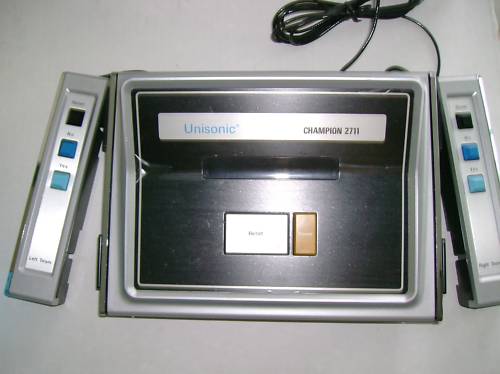
If you looked at it you might think, right, this machine only has 8 control buttons on it. The three on the controller and the two on the main unit.
Except it doesn't. It only has four things that would classify as control buttons, two for each player. So you could play Pong on it (actually, you can't for reasons I'll explain later) but you can't play anything requiring three button input (you could have press both simultaneously to fire)
On the main console itself there are two buttons. The orange one is the power switch. The big white one is a reset button which is connected to the CPU Reset, so it's basically the same as turning the power off and on.
One each controllers there are three buttons. What you can't see on this picture (I couldn't find a sharper one) - unless you squint is that the black buttons at the top are also reset buttons. So of the somewhat minimal three buttons on each controller, one of them is useless - all it means is you don't have to reach for the system box when you want to reset the console.
The two buttons that do work are labelled "No" and "Yes". As you can see, to compound the design decision they are logically the wrong way round - think about every dialogue box you see, the 'Yes' option is normally the Primary one.

If you remove the bits you have to have - the ROM Chip, the CP1610 CPU, the 8800 Graphics processor and the pair of 256 x 4 RAM Chips there's virtually nothing left. A 7402 (Quad 2 input NOR), a 7406 (Hex inverter) and a SN74367AN (A hex tristate driver).
(The first two suggest (perhaps) that they are Oring two lines together, inverting those outputs and using a third NOR gate to produce the result, possibly inverting again. What the Tristate driver is for I don't know - perhaps to deal with voltage loss on the cables ? Guess ?)
This switch layout is actually the only detail about this machine you can't derive from the component list.- which of those four Yes/No buttons is which CP1610 pin, and what the logic level is coming back in. You could use a NOR gate and test for button release.
I don't know this, so all the button testing will go through a routine which will standardise this.
No comments:
Post a Comment